Electronics & Tools
Building a kinetic sculpture: A journey from sketches to a motorized vehicle.
Concept & Design
Assignment: Create a kinetic structure using a motor.
I decided to build a simple motorized car. I started with a hand sketch to visualize the chassis, wheel placement, and drive mechanism.
Using Fusion 360, I modeled the chassis (25cm x 15cm) and 17cm wheels, designing a pulley-type mechanism to transfer power from the motor to the wheels.
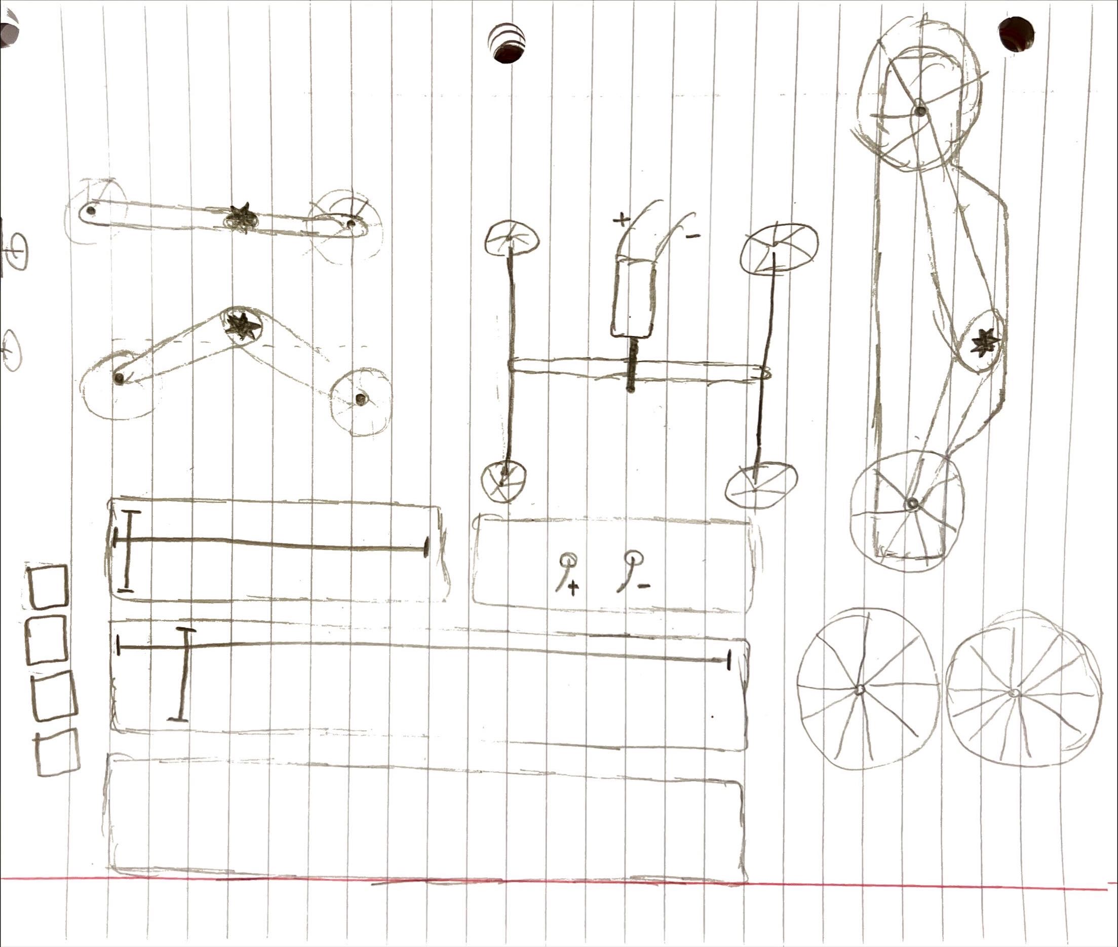
Initial Concept Sketch
Fabrication & Iteration
Laser Cutting
I cut the chassis and wheels from cardboard using the laser cutter. The design featured 4mm axle holes positioned strategically for balance.
The Flaw
The initial pulley system failed. The rubber bands would slip off the motor shaft after a few rotations, rendering the drive system useless.
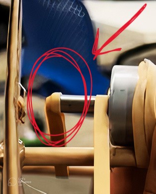
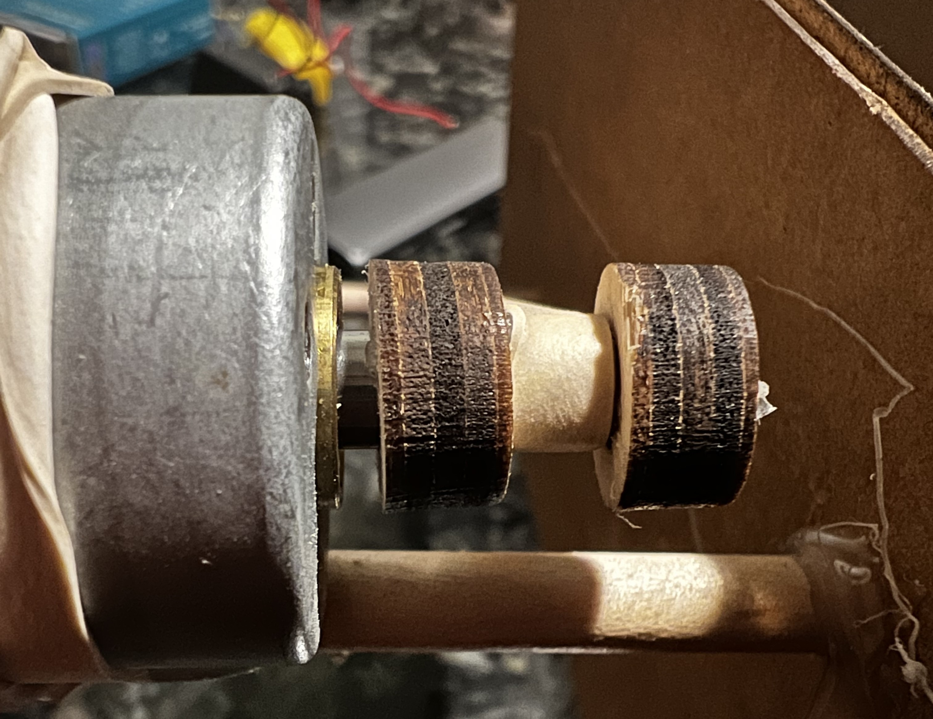
The Engineering Fix
To combat the slippage, I measured the motor shaft (6mm) with calipers. I designed a custom adapter in Fusion 360: a 13mm wooden disc with a precise 6mm friction-fit hole.
I cut this piece using the laser cutter at 100% Power / 12.5mm/s Speed to ensure a clean edge. This adapter kept the belt securely in place.
Final Demonstration
Retrospective: What I'd Change
The design is purely functional but lacks polish. It currently resembles a kindergarten project; future iterations would focus on a sleeker, enclosed chassis.
The single motor struggled on rough surfaces. Upgrading to a higher-torque motor or a dual-motor setup would improve reliability.
The cardboard wheels had poor grip. Adding rubber tires or coating the wheels in silicone would drastically improve handling.
Cardboard is great for prototyping but lacks durability. Moving to acrylic or plywood for the final chassis would increase structural integrity.