Electronic Output Devices
Controlling high-power peripherals: Neopixel Arrays, Servo Motors, and Memory Management.
Project Synthesis
This week challenges us to combine previous units (Microcontrollers & Inputs) into a cohesive system. I focused on two main outputs: Servo Motors (high-torque precision for steering) and Addressable LEDs (complex signaling logic).
Smart Vehicle Lighting
Voice-activated signaling system with memory optimization.
Phase 1: Validation
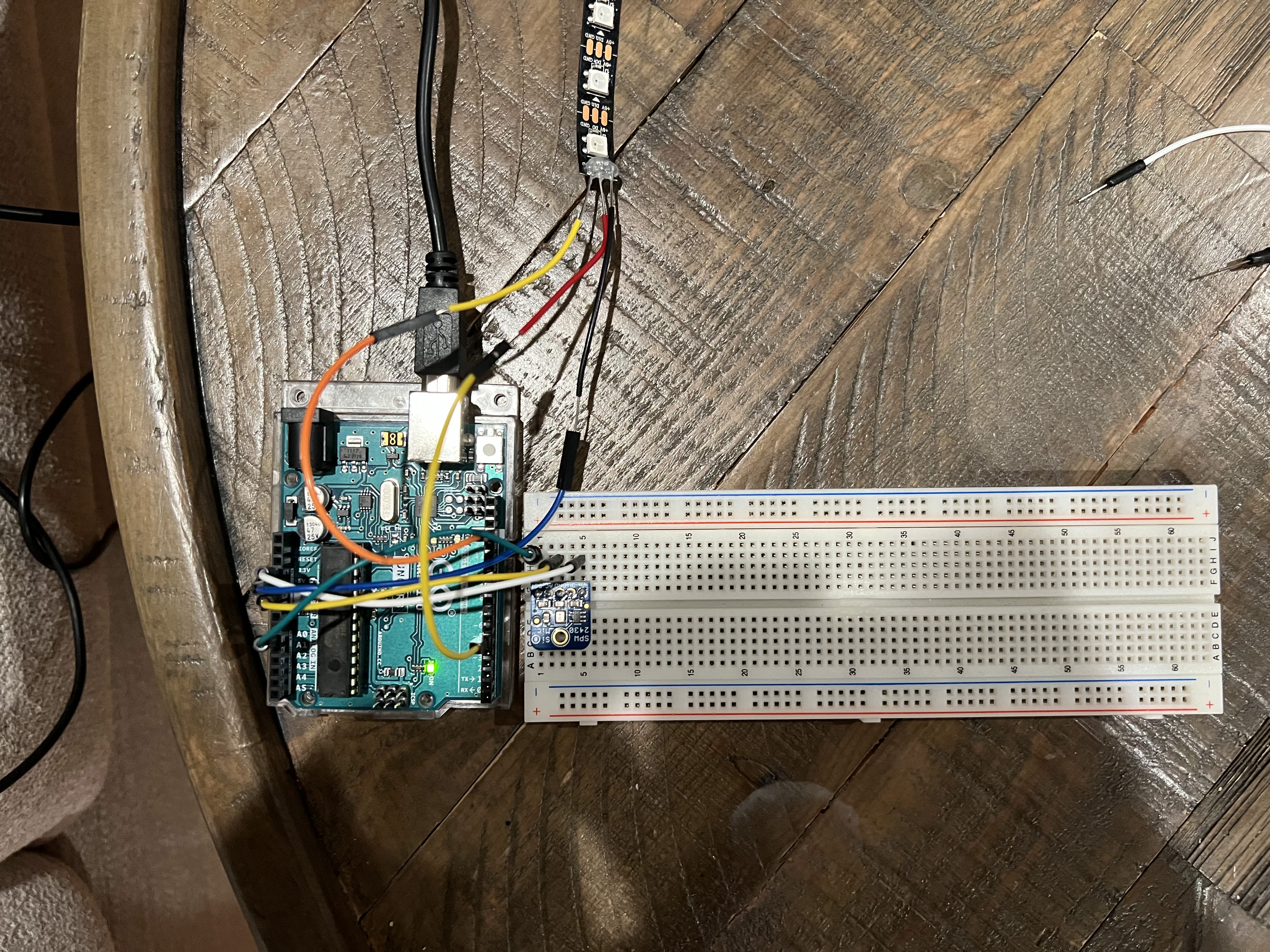
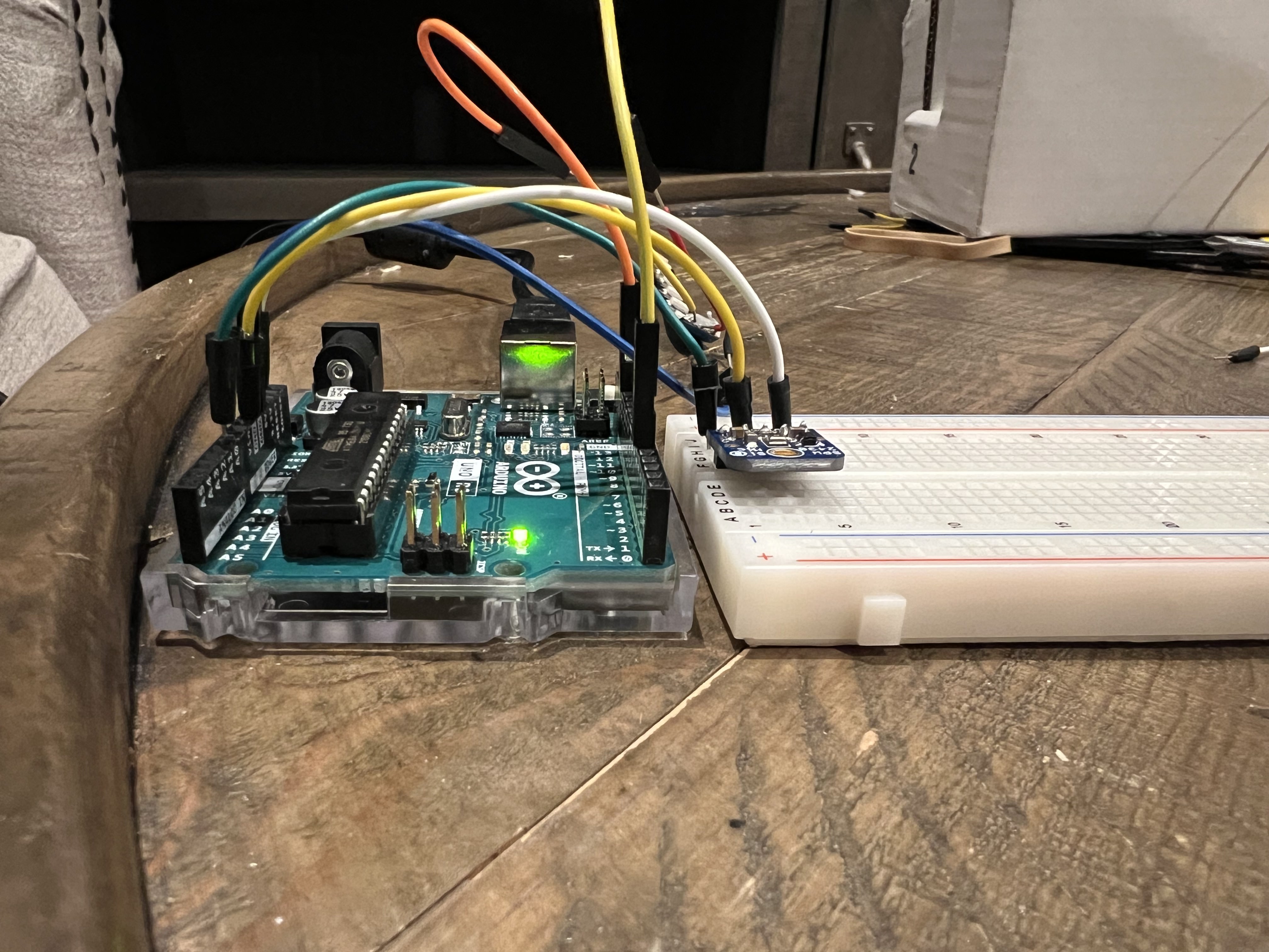
I started by validating a single LED circuit before moving to the complex strip. Simplicity first ensures the logic holds up.
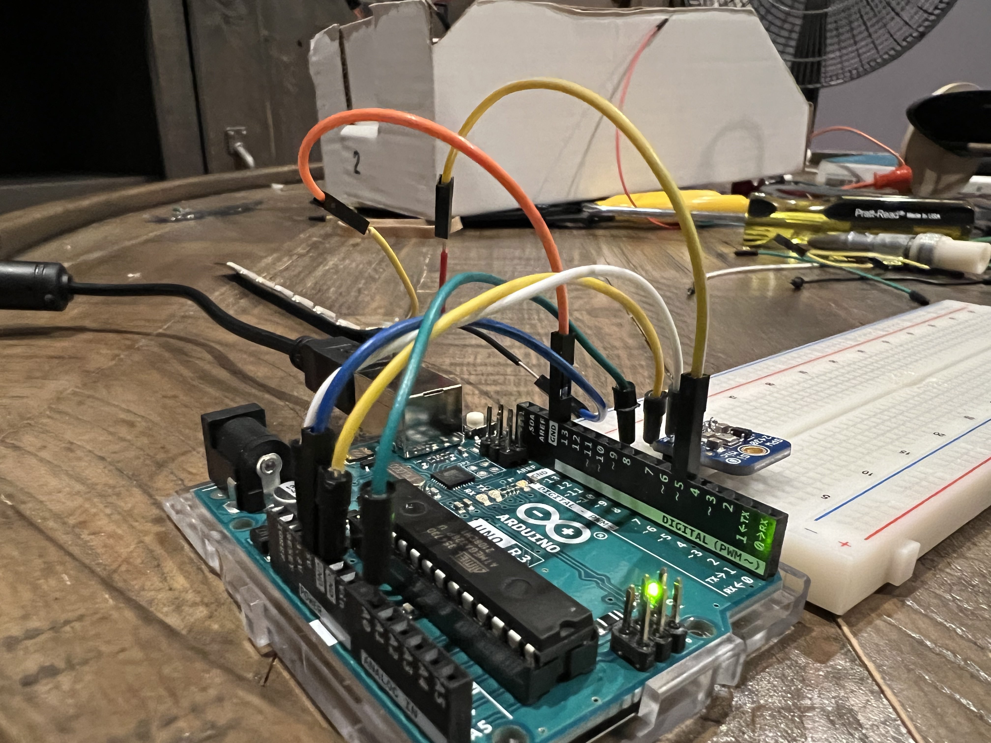
Phase 2: Integration
Using the Adafruit NeoPixel library, I built a full lighting system including turn signals, brake lights, and voice activation via microphone input.
Memory Management
Arduino has limited memory types. I optimized my code by explicitly managing these:
- Flash: Stores the program code. Persistent.
- SRAM: Temporary variables. I used
malloc()andfree()to dynamically manage heap memory during animations. - EEPROM: Slower, non-volatile storage. I used
EEPROM.write()to clear/persist state across reboots.
#include <Adafruit_NeoPixel.h>
#include <EEPROM.h>
#include <avr/pgmspace.h>

#define LED_PIN 5
#define LED_COUNT 7

Adafruit_NeoPixel strip(LED_COUNT, LED_PIN, NEO_GRB + NEO_KHZ800);

void loop() {
    // Clear EEPROM for clean state
    for (int i = 0; i < EEPROM.length(); i++) {
        EEPROM.write(i, 0);
    }

    microphoneReadings(startMillis, peakToPeak, signalMax, signalMin);

    if (peakToPeak >= 10) {
        // Dynamic Memory Allocation Example
        int *a = (int*) malloc(sizeof(int));
        int *b = (int*) malloc(sizeof(int));
        *a = 4; *b = 2; // Start from center

        for (int i = 0; i < 3; i++) {
            strip.setPixelColor(*a, 255, 255, 255);
            strip.setPixelColor(*b, 255, 255, 255);
            strip.show();
            delay(75);
            *a += 1; *b -= 1; // Expand outward
        }

        // Critical: Free memory to prevent leaks
        free(a);
        free(b);

        turnSignal(0); // Right
        turnSignal(1); // Left
        brakeAnimation();
    }
}
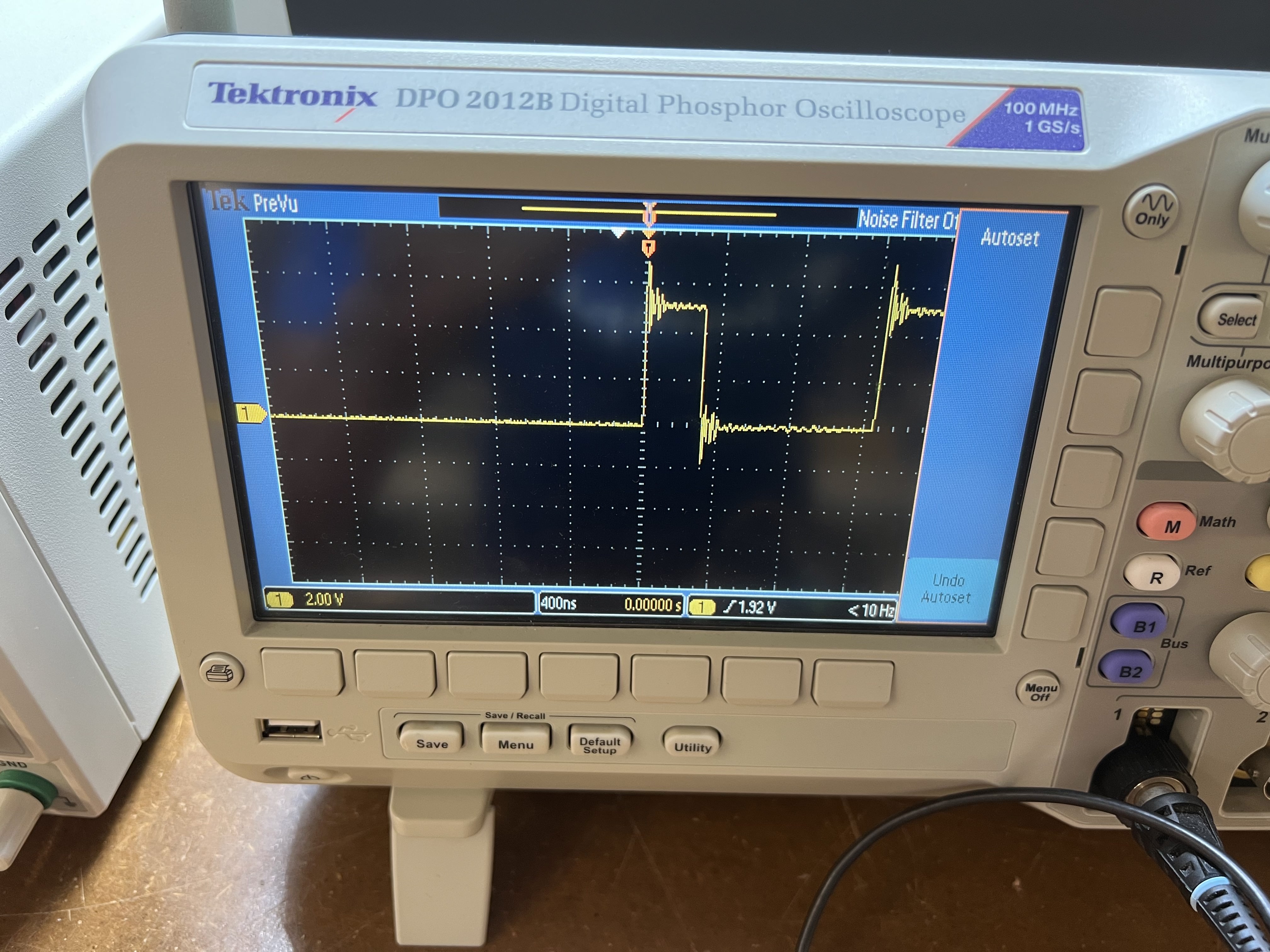
Oscilloscope Analysis
Visualizing Pulse Width Modulation (PWM) signals.
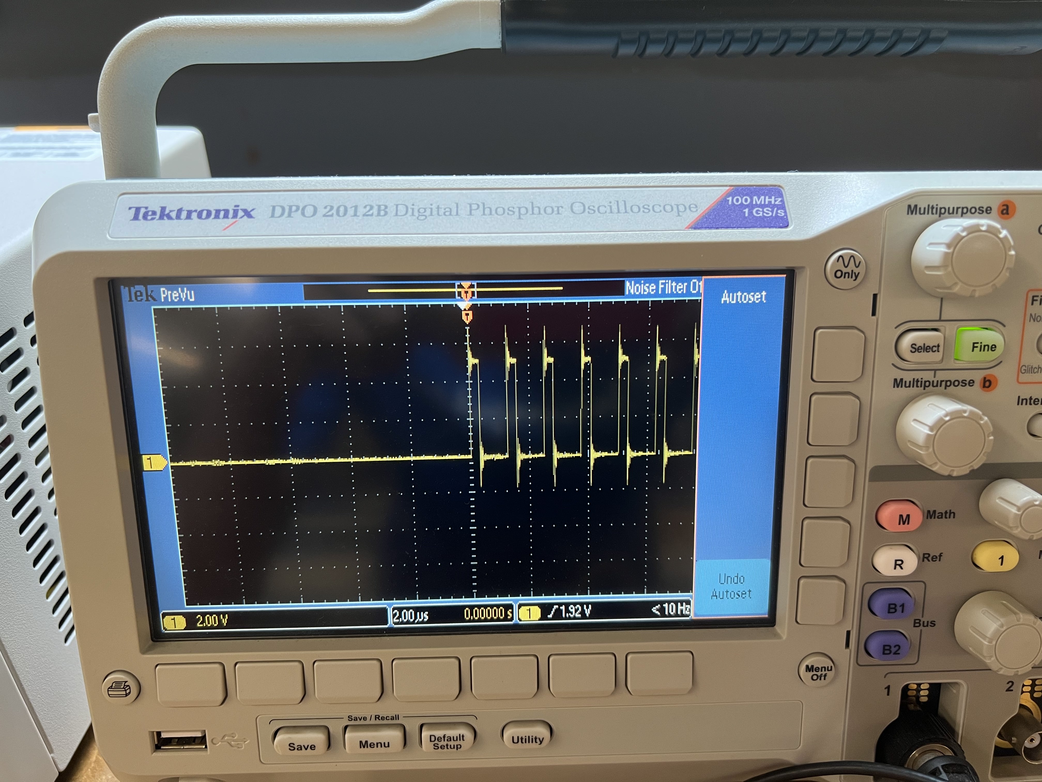
An oscilloscope allows us to visualize electrical signals over time. Initially, I saw only flat lines because the frequency was too high for my settings.
After calibrating the time-base, we captured the PWM (Pulse Width Modulation) signal. This "on-off" switching is how digital microcontrollers simulate analog voltages to dim LEDs or control motor speeds.
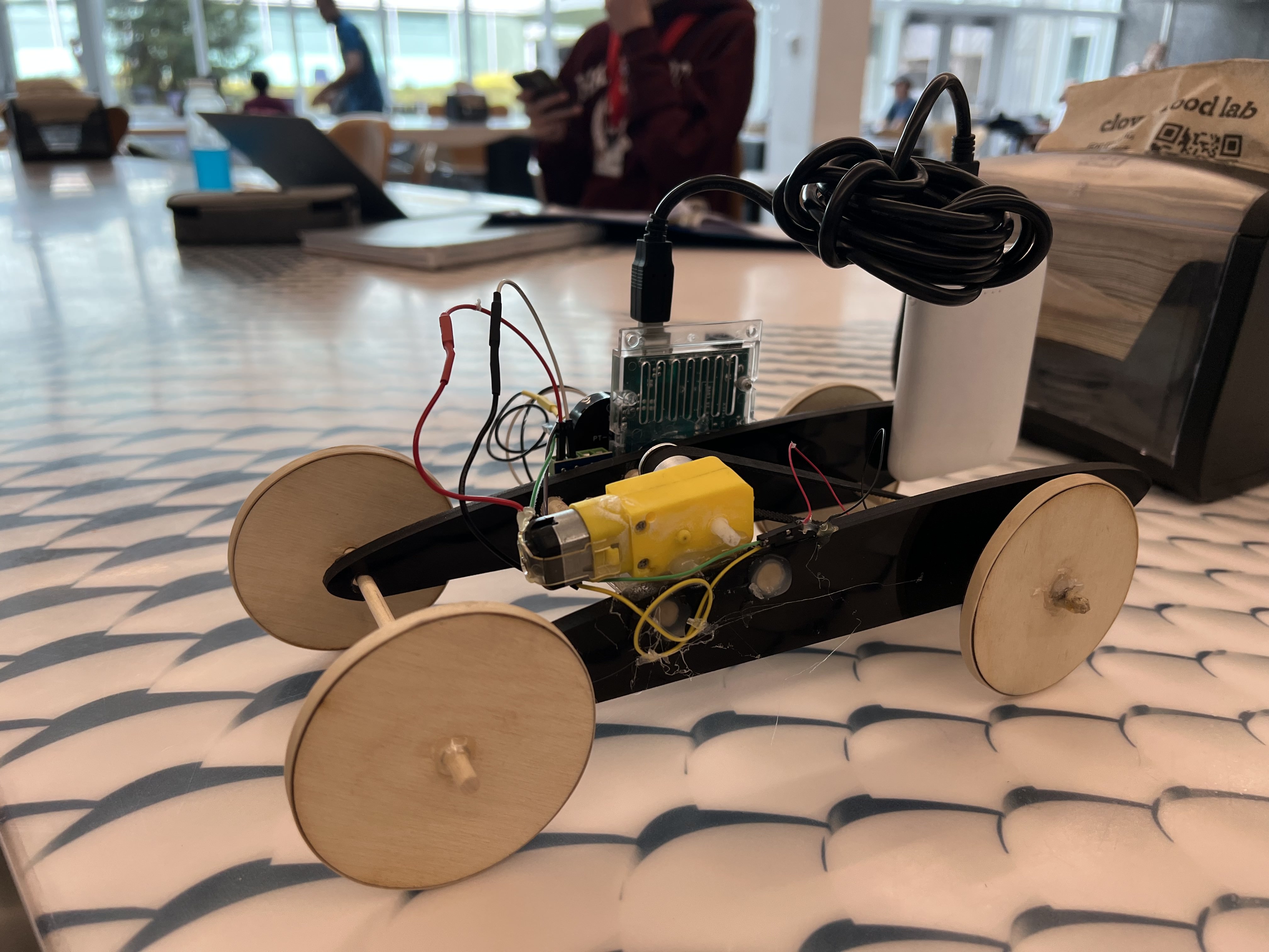
Related Integration
Piezo-Electric Car
Revisiting the car from the Microcontroller Programming unit. This device takes physical vibration (Piezo) as input and triggers a buzzer/motor output.
.png)
Preparation for Week 8: CNC
.png)
.png)
.png)